Budget Gesture-Sensing Glove

So one day, I was casually browsing the Adafruit Wbsite, and one thing just popped in front of me…
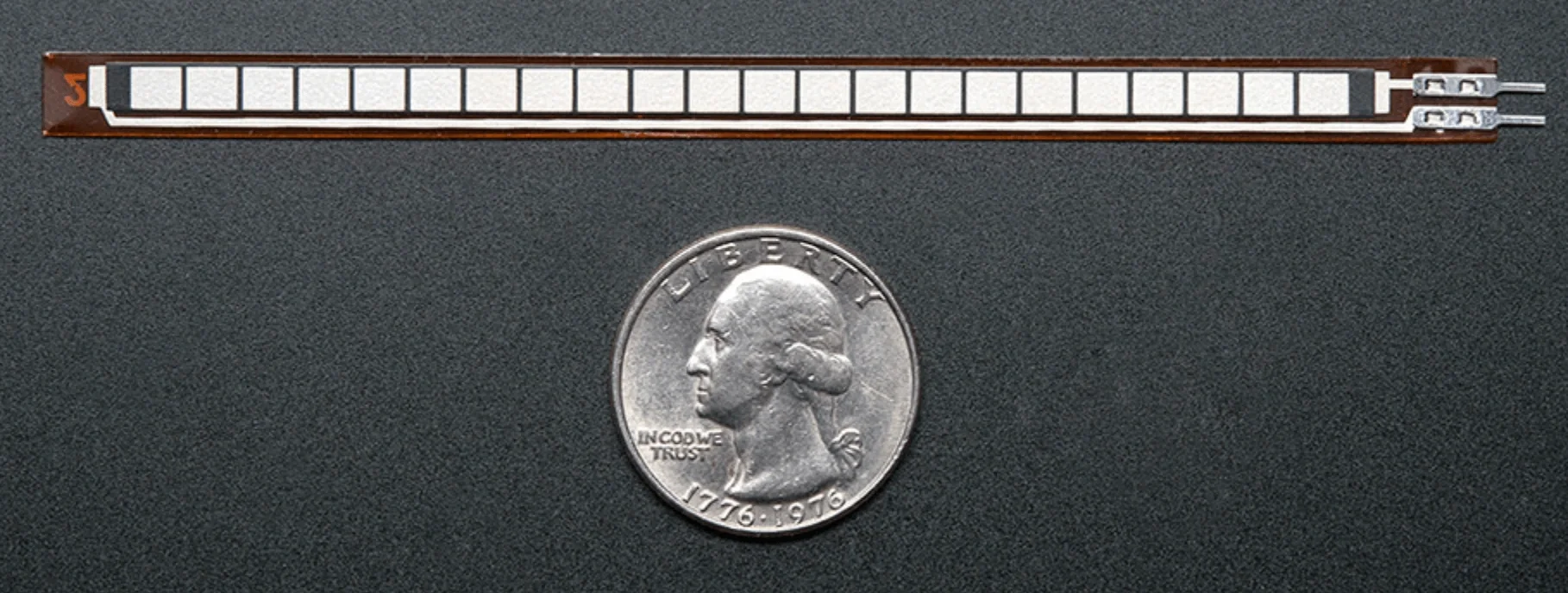
The Flex Sensors & Circuit Design⌗
So those flex sensors change their resistance according to the amount they flex. And their resistance is on the magnetite of $10k \Omega$. I designed a simple nested voltage divider with five $25k \Omega$ resistors:
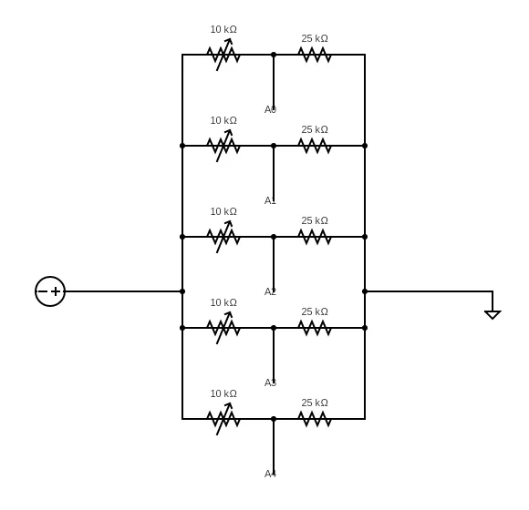
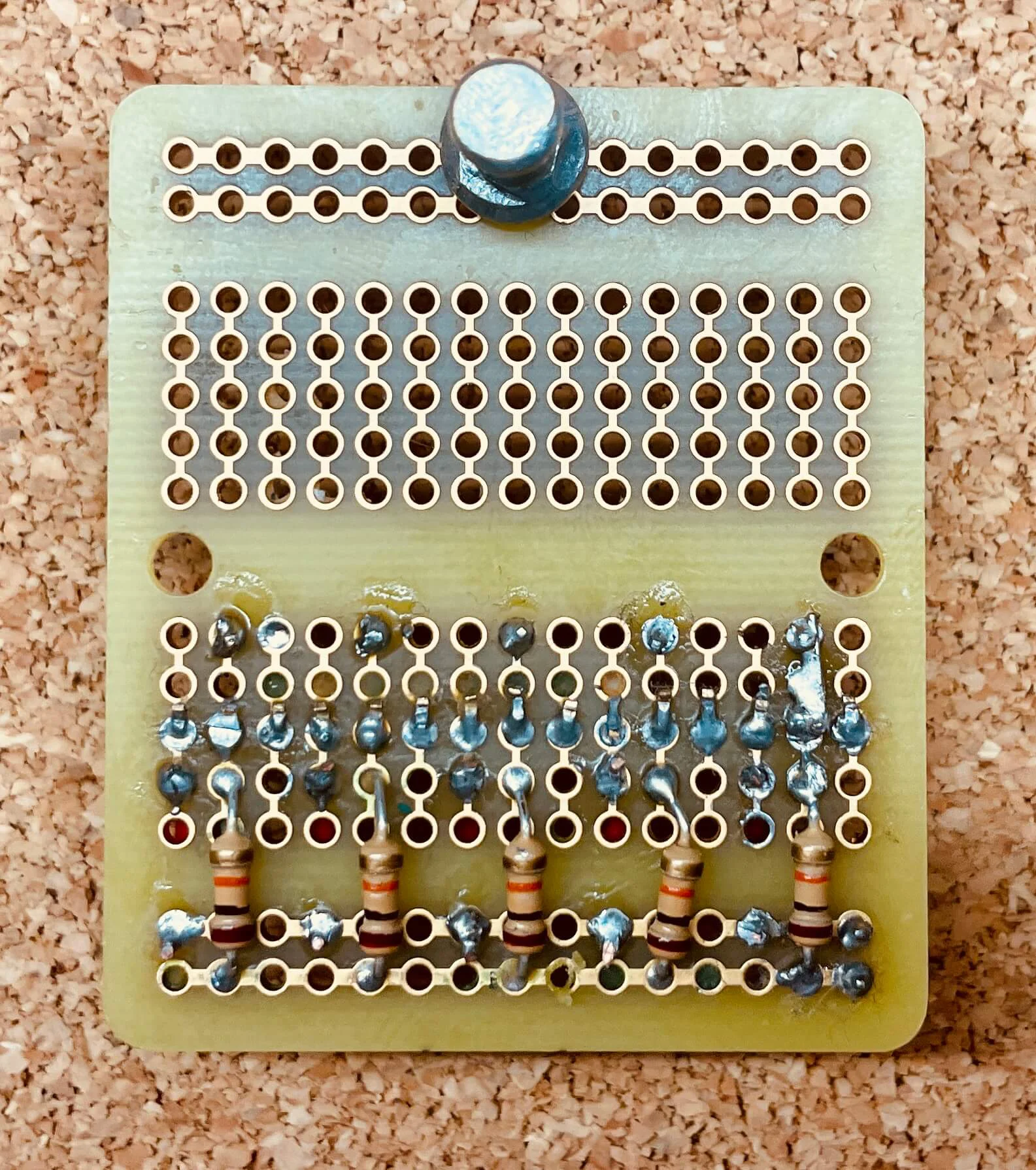
This design simplifies the circuit where there is no need to connect each flex sensor with individual VCC and GND as they are now all sharing the same VCC&GND. I soldered everything on a prototype board:
|
|
|---|---|
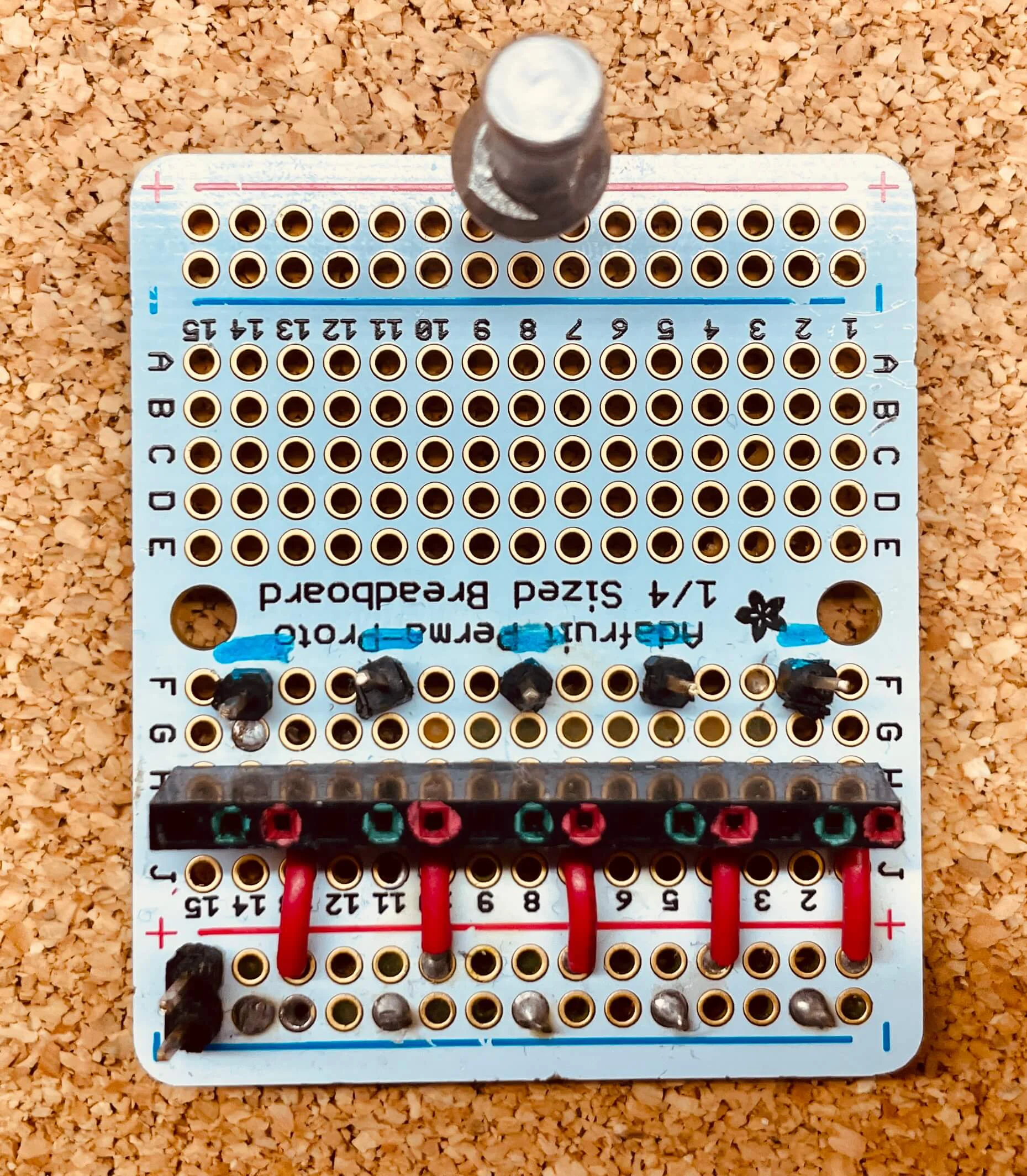
| FRONT | BACK |
The sockets labeled with green are for the analog connection with the microcontroller, and the blues and reds are for the connection of the flex sensors. VCC&GND provided by the board will be connected to the +/- rail.
The Microcontroller⌗
The microcontroller I first used is an FRDM-KL46Z which requires me to write low-level scheduling algorisms(I used polling, btw). However, that was for the Embedded class I was taking. Instead, it would be much easier just to use a Raspberry Pi Pico; why Picos specifically? Well, I like the look of them…
Unfortunately, Pico only has 4 ADCs, and only three of them are usable(GP26,27,28), so unless I am able to utilize concurrency by scheduling a small time interval precisely to a sensor to make one analog pin able to serve multiple sensors, the max amount of fingers I can sense is three.
These are pretty good ADCs though, they are 12-bit precision so that I can get voltage data ranging from 0 to 4096(2^{12}).
The Mapping Function⌗
As mentioned above, the data from the analog pins are just numbers ranging from 0 to 4096, which does not mean much for humans. Naturally, we want the percentage to represent how much the finger is bent. As a dummy demo, I just wrote a piece-wise linear function(which is definitely off by a lot as the resistance change is not linear). Firstly I print out the value when the flex sensor is in its natural position, which is around 500/4096, and when it is fully bent, it is around 250/4096. Thus the mapping function looks like this:
int flexmapping_long(int analogflex){
  if(analogflex>500){
    return 0;
  }
  else if(analogflex<250){
    return 100;
  }
  else{
    return -analogflex*0.4+200;
  }
}
The more appropriate way will be to measure the analog read at different angles, collecting as many data points as possible, then run a polynomial fit. Here is a demo of the glove working: The mapping function behaves surprisingly well!
The Glove Design⌗
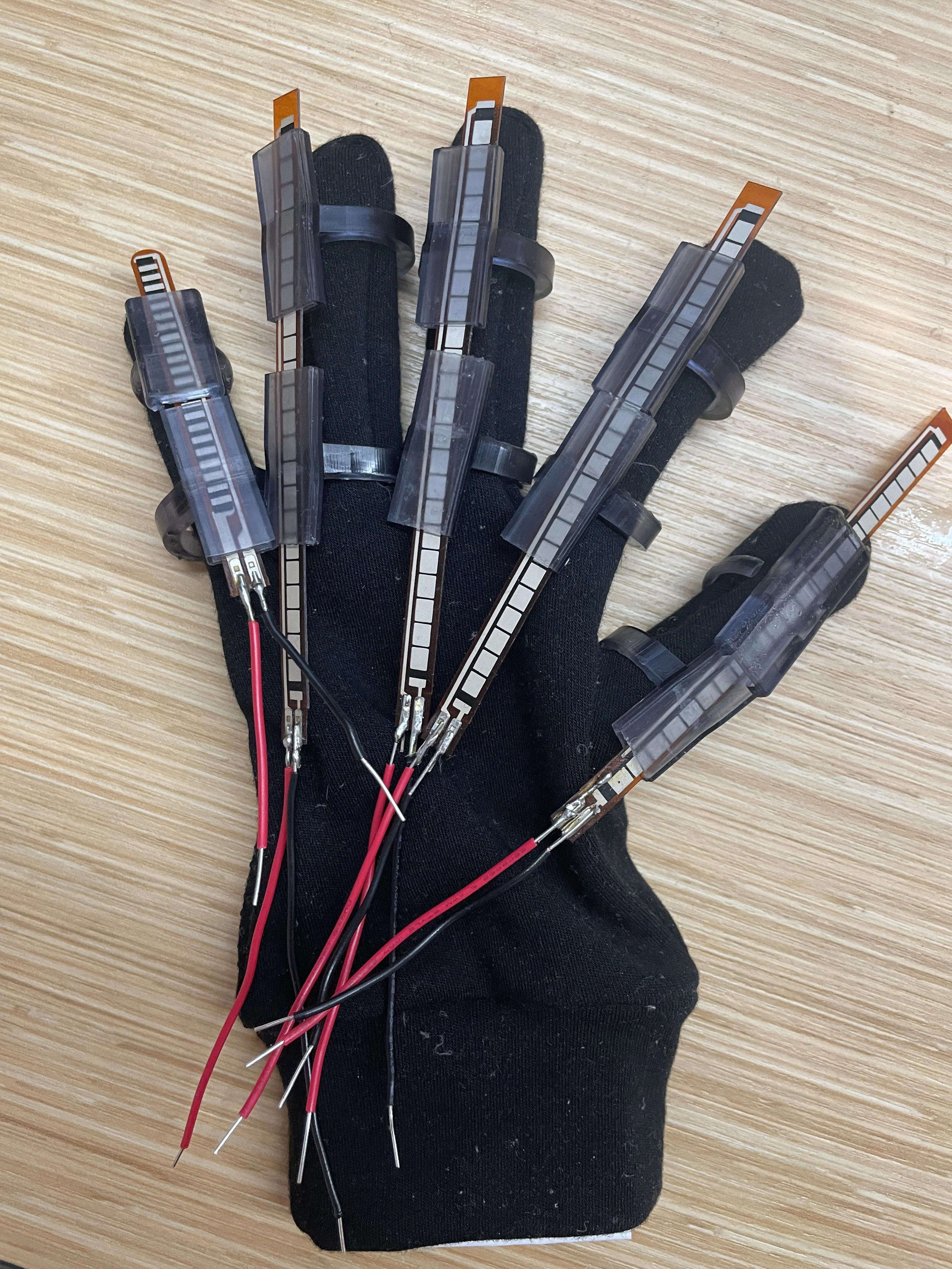
One thing about wearable device design is that it is just really hard to have something reliable to put on a lump of moving meat.
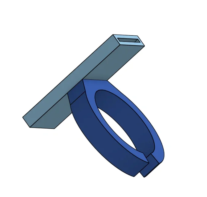
The initial design has a couple of 3d printed harness rings that hold the flex sensor in place:
|
|
|---|---|
| Glove | Harness 3D Model |
But the sensors will slide around, making only parts of the sensors really bent, but most parts are straight, so the reading was highly inaccurate.
So turns out the better way is to have a two-layer glove and just put the sensors inside the layers. Or I can stitch a hollow fabric tube or something on each finger.
Conclusion⌗
I actually turn out decided to discontinue the project for a couple of reasons. Firstly, each figure only has one degree of freedom, so the Unity model will probably just be boring and like a dead body’s hand. Secondly, spending time making a better sensor holder does not interest me. And, well, apparently, making a gesture-sensing glove is basically the first thought of many people when they found these sensors, so as I figured out, many people already have done similar projects; I am just no longer motivated. But designing the voltage divider board was fun tho.
Here is a demo video from my embedded class(I made it as artistic as possible to earn points for a very much unfinished project):